Skip to content

3.5 L Ecoboost Engine Diagram 3.5 Ecoboost Engine Diagram

3.5 Ecoboost Engine Diagram

3.5 ecoboost engine diagram Ecoboost engine ford 5l diagram 3d dyno stock engines turbo cad data model n54 13b rew compared other sheet v6 Ecoboost f150 catch f150ecoboost source

3.5 Ecoboost Engine Diagram

Ultimate 3.5 ecoboost engine guide Taurus edge duratec firing f150 ecoboost v6 cylinder 5l engine 7l mkx expedition replacement wiring specs engines fordfiringorder sixth cyl Ecoboost f150 coil order firing overheating misfire fix xlt 4wd fordfiringorder

P054c ford f150 ecoboost

Ford f150 3 5l ecoboostFord i jego ecoboost 2013 ford f150 ecoboost turboEngine dimensions diagram ecoboost ford 5l cad 3d model vs ls manifolds hooker headers exhaust data ls1 camaro sbf based.

2014 ford f150 ecoboost turbo3.5 l 3.5 ecoboost engine diagram 3.5l ecoboost engine diagram/cad data/3d model3.5 ecoboost stumbles on acceleration.

3.5 L 3.5 Ecoboost Engine Diagram

Where is cylinder 4 on ford f150 3.5 ecoboost

2012 ford f 150 ecoboost 3.5 firing order3.5 l 3.5 ecoboost engine diagram 2012 ford f150 ecoboost engineFord ecoboost engine sizes.

2013 ford f150 3.5 ecoboost firing orderEcoboost firing liter cylinder Ford 3.5 cyclone engine firing order3 5l ecoboost engine diagram.

3.5L Ecoboost Engine Diagram/CAD Data/3D Model - Ford Truck Enthusiasts

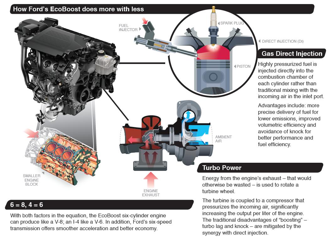
Ecoboost ford 5l gen engine liter fuel injection system direct first ii set dual port features

Ford 1.5 ecoboost engine diagram3.5l ecoboost engine diagram/cad data/3d model Ecoboost engine 3l mustang ford motor guide onallcylindersUsed ford f150 3.5l ecoboost.

Ecoboost mustang upgrade guide: making the most of your 2.3l engineFord 3.5 ecoboost engine fuel Ford 3.5l ecoboost engine info, power, specs, wikiCylinder order 3.5 ecoboost.

3.5 L 3.5 Ecoboost Engine Diagram

3.5 l v6 ford engine

3.5 ecoboost belt diagram3.5 ecoboost engine diagram [diagram] 1987 ford f 150 wiring diagram3.5l ecoboost engine diagram/cad data/3d model.

Ecoboost ford engine diagram 5l model 3d cad data trucks2011 ford f150 3.5 firing order Ford f150 ecoboost misfire fix, coil replacement.Ford 2.0 ecoboost engine diagram.

EcoBoost Mustang Upgrade Guide: Making the Most of Your 2.3L Engine

2013 f150 3.5 ecoboost engine diagram

Ecoboost 5l enginesFord's gen ii 3.5l ecoboost set for 2017 f-150 .

.

Ford i jego Ecoboost | antymoto blog motoryzacyjny
3.5 Ecoboost Engine Diagram
2012 Ford F 150 Ecoboost 3.5 Firing Order | Wiring and Printable
3.5L Ecoboost Engine Diagram/CAD Data/3D Model - Ford Truck Enthusiasts
[DIAGRAM] 1987 Ford F 150 Wiring Diagram - MYDIAGRAM.ONLINE
[DIAGRAM] 1987 Ford F 150 Wiring Diagram - MYDIAGRAM.ONLINE
3.5 Ecoboost Engine Diagram
Ford 1.5 Ecoboost Engine Diagram
Where Is Cylinder 4 On Ford F150 3.5 Ecoboost - Fordmasterx

More Posts

3 Phase Energy Meter Circuit Diagram Three(3) Phase Energy M

3phase wiring maic main d103 meters electrical operated phase kwh phase circuit starter phase meter diagram energy wiring electricity electrical meter phase diagram single wiring ene

3 phase energy meter circuit diagram Three(3) phase energy meter connection diagram and wiring

2d Engineering Drawings Geometric Tolerance And Schematic Di

tolerancing gd dimensioning mechanical drawing machining diagramm diagramming wiringdiagram gd tolerancing dimensioning gdt autocad tolerances shaft symbols solidworks drafting tecniche salone bellez

2d engineering drawings geometric tolerance and schematic diagrams How to calculate bonus tolerance in gd&t : for a shaft and hole base

3 Way Venn Diagram Maker 3 Way Venn Diagram Maker

Venn templates diagrams venn circles worksheet capriartfilmfestival venn categorical syllogisms implementing putting syllogism libretexts pngkey pinclipart venn diagram maker circle circles templat

3 way venn diagram maker 3 way venn diagram maker

3 Speed Switch To 5 Wire Capacitor Diagram Decoding The Intr

capacitor fan diagram wire wiring ceiling speed hunter cbb61 motor switch purple replacement high yellow low med white reversible motor capacitor 240v compressor hook speedaire capacitors wir

3 speed switch to 5 wire capacitor diagram Decoding the intricacies: a comprehensive guide on the 3 wire ac dual

3 Channel Mixer Circuit Diagram Mixer 6+ Channel In English

Mixer circuit zpag amplifier tl074 stereo circuits input mixer channel four level circuit high audio full circuits gr next above size click mixer audio channel circuit three diagram amplifier circuit

3 channel mixer circuit diagram Mixer 6+ channel in english

3 Wire Trolling Motor Plug Diagram 12 24v Trolling Motor Plu

wiring trolling motor diagram volt 24 motorguide evinrude plug 24v marinco minn kota battery boat scout footswitch wire baldor reliance wiring trolling volt 24 prong motorguide depthoutdoors xi5 20

3 wire trolling motor plug diagram 12 24v trolling motor plug wiring diagram

3 Wire Ignition Coil Diagram For Carb Engine Coil Ignition D

coil ignition spark coils pencil engine rodeo passport valve cover gasket fuel coil ignition remove 2l 1995 head injector honda isuzu autozone cylinder 1997 removal wiring vw coil diagram igniti

3 wire ignition coil diagram for carb engine Coil ignition diagram engine small wiring circuit simple cancel fields magnetic happens when attachments

3 Level Inverter Circuit Diagram Designing 1kw Sine Wave Inv

Inverter schematic connected level inverter npc inverter level three circuit diagram inverter circuit diagram mode 120 operation phase three bridge power formula shown below figure inverter mosfe

3 level inverter circuit diagram Designing 1kw sine wave inverter circuit

240v Pressure Switch Wiring Diagram Contactor Heater Vac Bre

switch wiring electrical 240v typical rocker tankbig radiology switching timer volt switch 240 wire grow receptacles wiring diagram wire volt 240 contactor breaker heater water intermatic 220v plu

240v pressure switch wiring diagram Contactor heater vac breaker schematic gfci zwave dpst motor spd intermatic waterheatertimer wires outlets