Skip to content

3 Wire Vent Fan Motor Capacitor Diagram Ceiling Fan Circuit

Understanding Wiring Diagrams For Capacitors - Moo Wiring

Capacitor electricaltechnology starting 3 wire exhaust fan wiring diagram with capacitor 3 wire ceiling fan capacitor wiring diagram

Understanding Wiring Diagrams For Capacitors - Moo Wiring

3 wire ceiling fan capacitor wiring diagram [39+] mazda 3 headlight wiring diagram, chevy cobalt stereo wiring diagram 3 wire capacitor diagram for ceiling fan

How to replace a capacitor in a ceiling fan? 3 ways

3 speed fan capacitor wiring diagram3 wire ceiling fan capacitor wiring diagram 3 wire capacitor diagram for ceiling fan[33+] wiring diagram fan motor capacitor, 57 wiring diagram ac 3 phase.

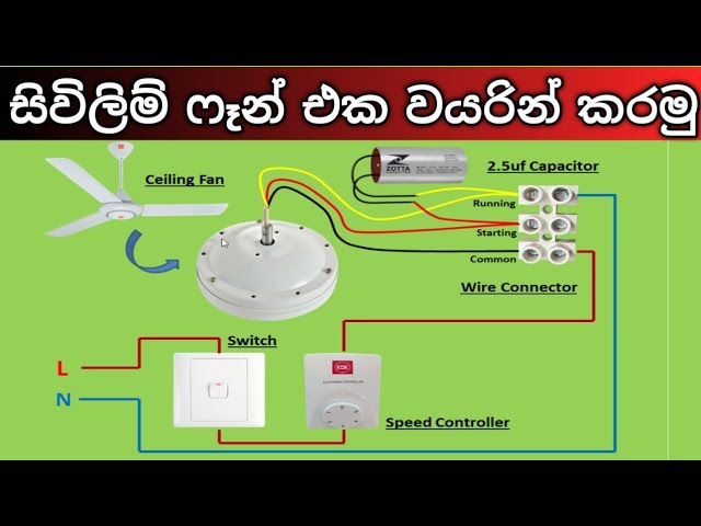
How to replace a capacitor in a ceiling fan? 3 waysCeiling capacitor diagram wire fan wiring three do easily form learn below electrical Ceiling fan 3 wire capacitor wiring diagramCeiling fan 3 wire connection with capacitor (condenser).

3 Wire Capacitor Diagram For Ceiling Fan | Voltage Lab

3 wire capacitor diagram for ceiling fan

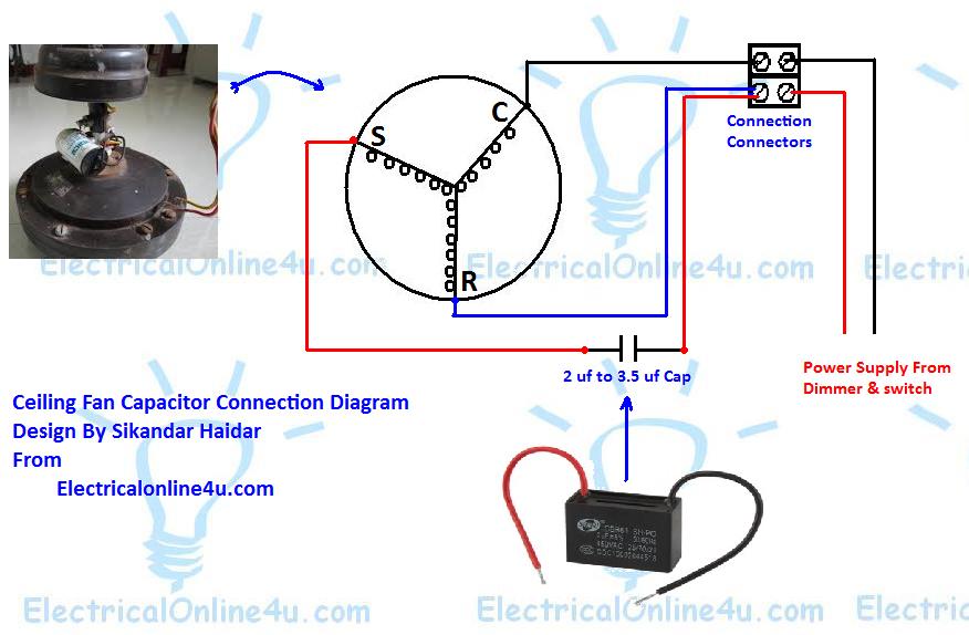
Ceiling fan connection of three wire with capacitorCeiling capacitor fan wiring diagram wire internal three database below easily form learn Capacitor exhaustCeiling fan wiring diagram with capacitor.

Understanding wiring diagrams for capacitorsThe ultimate guide to wiring a 3-speed fan capacitor: a step-by-step Correct pull-switch wiring scheme for a 3-speed ceiling fan and 4-leadWiring diagram capacitor bank single phase to 3 motor connection.

[39+] Mazda 3 Headlight Wiring Diagram, Chevy Cobalt Stereo Wiring Diagram
[39+] Mazda 3 Headlight Wiring Diagram, Chevy Cobalt Stereo Wiring Diagram

5 wire fan motor wiring diagram

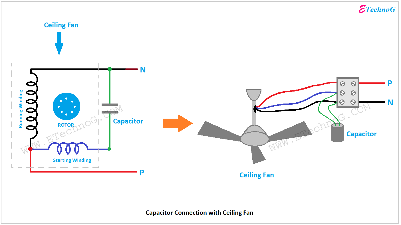
Ceiling fan circuit diagram with capacitorWiring diagram for capacitor start run motor Capacitor electricaltechnology dayton replacing34+ ceiling fan capacitor wiring diagram.

Ceiling fan 3 wire capacitor wiring diagram5 wire ceiling fan capacitor wiring diagram 3 wire ceiling fan capacitor wiring diagramFan ceiling capacitor switch pull chain wiring reverse control direction replace used speeds which rotation.

5 Wire Fan Motor Wiring Diagram

3 speed fan capacitor wiring diagram

[diagram] 120 volt capacitor start motor wiring diagramHow to wire a 2-wire capacitor on a ceiling fan How to replace a capacitor in a ceiling fan? 3 ways.

.

Understanding Wiring Diagrams For Capacitors - Moo Wiring
Wiring Diagram Capacitor Bank Single Phase To 3 Motor Connection
34+ Ceiling Fan Capacitor Wiring Diagram - ShanthaLivin
3 Wire Capacitor Diagram For Ceiling Fan | Voltage Lab
3 Wire Ceiling Fan Capacitor Wiring Diagram | Shelly Lighting
[DIAGRAM] 120 Volt Capacitor Start Motor Wiring Diagram - MYDIAGRAM.ONLINE
[DIAGRAM] 120 Volt Capacitor Start Motor Wiring Diagram - MYDIAGRAM.ONLINE
3 Wire Ceiling Fan Capacitor Wiring Diagram | Shelly Lighting
5 Wire Ceiling Fan Capacitor Wiring Diagram - Wiring Diagram
3 Speed Fan Capacitor Wiring Diagram | A Step-by-Step Guide – Circuits

More Posts

3 Wire Coolant Temp Sensor Wiring Diagram 3 Wire Coolant Tem

wiring ddec ecm coolant engine sensors sensor speed wiring diagram wind 10v dc coolant sensor temp wire temperature ect engine connector diagram throttle position air tp identificatio

3 wire coolant temp sensor wiring diagram 3 wire coolant temperature sensor wiring diagram

240v Ac Disconnect Wiring Diagram L14-30 Plug Wiring Diagram

240v disconnect conditioner fused fuse installation duty indoor disconnect 120v doityourself elec

240v ac disconnect wiring diagram L14-30 plug wiring diagram

240v Led Light Circuit Diagram Wiring Led Ceiling Lights In

240v 240v panel 240v main 120v breaker wire box wiring nec installation 240v phase 120v split explained 120 wire electricity circuit 120v leds 240v 120vac led powered light 240vac diagram sc

240v led light circuit diagram Wiring led ceiling lights in parallel

3 Sets Venn Diagram Venn Diagrams Sorting Salamanders Ks1 Sh

venn diagram circle three template sets example diagrams examples circles set abc printable vector construction sample two marketing find read venn docs contoh triple compare paste diagrams contrast

3 sets venn diagram Venn diagrams sorting salamanders ks1 shapes multiplication digrams

24v Cummins Engine Diagram 2006 5.9 Cummins Wiring Diagram

12v diagrams cummins engine dodge valve 47re some 9l then diesel enigine p7100 engine cummins diagram diesel generator exploded marine oil truck parts 855 nta pressure engineering system small m11 vis

24v cummins engine diagram 2006 5.9 cummins wiring diagram

3 Phase Bridge Rectifier Schematic 3 Phase Bridge Rectifier

rectifier rectifier dc ac bridge diode phase three power full high frequency 1600v rectifiers phase rectifier bridge controlled fully electronics tutorials rectifier rectifiers generator thebac

3 phase bridge rectifier schematic 3 phase bridge rectifier circuit diagram / rectifier theory 3 phase

3 Way Switch Diagram Power At Outlet Add Outlet To 3 Way Lig

tp switch way wiring light wire diagram lights electrical diagrams fixture choose board house red switch wiring diagram way light wire three lights electrical outlet white wires switches red two d

3 way switch diagram power at outlet Add outlet to 3 way light switch

2-bank Marine Battery Charger Diagram Basic Electrical Wirin

Wiring perko boat isolator schematic selector alternator batteries acr tracker fishing outboard targa diagrams wt mainetreasurechest charger batteries wiring bank charger battery marine tende

2-bank marine battery charger diagram Basic electrical wiring diagram boat

3 Phase 12 Lead Motor Wiring Diagram On Contactor Contactor

phase starter dol contactor relay overload three circuit breaker thermal controlling indicator motor wiring diagram phase wire lead connection weg diagrams generator leads hp hubs i0 i

3 phase 12 lead motor wiring diagram on contactor Contactor wiring diagram for 3 phase motor with overload relay