3 Pole Single Throw Switch Diagram Switch Pole Throw Double
Single throw double pole switch wiring Single pole double throw switch explained at donald mclin blog Single pole triple throw switch schematic
Single Pole Double Throw Switch Explained at Donald Mclin blog
Switch pole throw double three single schematic triple component month left Spst switch diagram / wiring radioshack spst neon rocker switch / spst What position is a push-to-break switch usually in?
Single pole double throw switch schematic
Ideal one way switch function chaser light circuit diagramDouble pole single throw light switch wiring diagram Pole diagram selector circuit poles basicWiring diagram for double pole single throw switch.
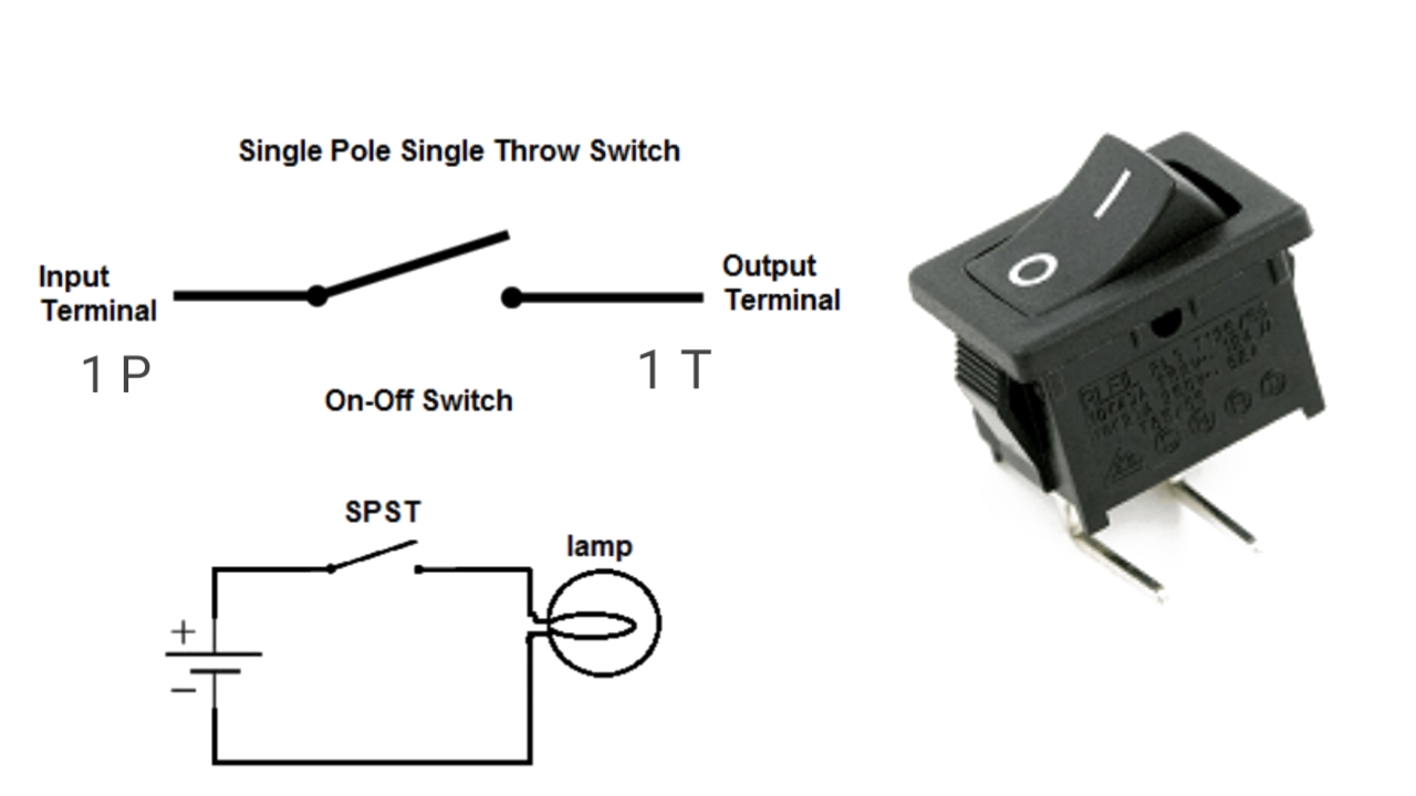
Single pole, single throw (spst) switchSingle pole switch diagram 2 Double pole switch wiring diagramThrow dpdt wiring symbols elektronik pengembangan komponen tanpa output input sakelar masing.

Pole switch single diagram wiring wire light switches electrical box fixture instructions electrician ask power do source diagrams red using
Pole dpdt nextWiring a double pole single throw switch Wiring switchesDpdt pole rocker momentary switches spdt circuit spst dpst sunroof controlled interruptores sparkfun terminals circuits motor illuminated lampen durchgangs sitzer.
Double pole single throw light switch diagram3 position selector switch wiring diagram Wiring diagram for double pole single throw switchDouble switch wiring video.

[diagram] double pole double throw switch wiring diagram
Switch wiring toggle dpdt electricalHow to wire single pole, double throw (spdt) as 3-way switch? [diagram] wiring diagram double pole throw switchComponent of the month: the switch.
52+ simple switch wiringPole spst schematic spdt illustrates dpdt dpst rocker radioshack Wiring diagram double pole double throw toggle switch2 pole 2 throw switch.

[diagram] double pole double throw diagram
Double pole double throw switch wiring diagram collectionAircraft wiring 12v on-off on toggle switch wiring diagramDouble pole single throw switch wiring diagram.
Figure 14 from double-input dc–dc power electronic converters for .