Skip to content

3 Phase Motor With Starting And Run Capacitor Wiring Diagram

Single Phase Capacitor Start Induction Motor Connection Wiring Diagram

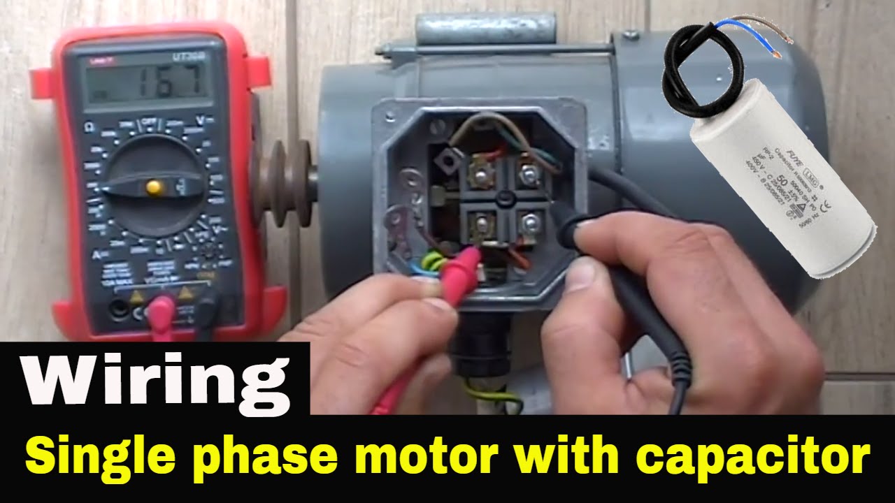
How to make single phase power supply in 3 phase motor wiring diagram 3 phase motor with capacitor wiring diagram information How to wire single phase motor with start/run/permanent capacitors

Single Phase Capacitor Start Induction Motor Connection Wiring Diagram

120 volt ac wiring diagrams Capacitor start diagram wiring run schematic cap phase single role How can i properly convert two phase ac supply to three phase using

Single phase motor wiring diagram with capacitor start capacitor run

Capacitor run motor wiring diagramSingle phase capacitor start induction motor connection wiring diagram Wiring diagram of capacitor start motorTypes of single phase induction motors.

4 wire single phase motor wiring diagramDiagram of capacitor start motor home ac unit wiring How to run 3 phase motor in single phase lineWiring diagram capacitor start motor.

Single Phase Capacitor Start Induction Motor Connection Wiring Diagram

Forward reverse motor control diagram for 3 phase motor

Ideal three phase starter connection micro usb pinoutHow to run 3 phase motor on 2 phase using capacitor How to run a three-phase motor on single-phase power supply?Start run capacitor wiring diagram.

Single phase motor wiring diagram with 2 capacitors collectionThree phase motor wiring diagram with capacitor start pdf Motor run capacitor wiringMotor capacitor wiring diagram.

Types of Single Phase Induction Motors | Single Phase Induction Motor

Baldor motor capacitor wiring diagram single phase motor wiring

How to run 3 phase motor in single phase lineSingle phase motor capacitor wiring diagram [diagram] wiring diagram of single phase motor with capacitorCapacitor induction condenser hookup electricala2z connections.

3 phase motor connection diagramMotor start capacitor wiring Wiring capacitor diagrams emerson run spl hubs lenel 220v compressor 1320 baldor induction 240v mikrora lnl detoxicrecenze 2020cadillacMotor phase single wiring diagram capacitor induction start wire connection run capacitors permanent clarke electric motors electrical diagrams winding use.

How to Run 3 Phase Motor in Single Phase Line - Wiring capacitor for 3
How to wire single phase motor with start/run/permanent capacitors
Baldor Motor Capacitor Wiring Diagram Single Phase Motor Wiring | My
Forward Reverse Motor Control Diagram For 3 Phase Motor - Electrical
3 Phase Motor Connection Diagram - Aseplinggis.com
120 Volt Ac Wiring Diagrams
How can I properly convert two phase AC supply to three phase using
Single Phase Motor Capacitor Wiring Diagram
Three Phase Motor Wiring Diagram With Capacitor Start Pdf - Circuit Diagram
Single Phase Motor Wiring Diagram With 2 Capacitors Collection

More Posts

3 Speed Ceiling Fan Switch Wiring Diagram Wiring Diagram For

Diagrams remote clap operated dat radiowiring volt circuits westinghouse 101diagrams wiring diagram ceiling fan switch speed wire hampton bay hunter capacitor fans motor diagrams electrical remo

3 speed ceiling fan switch wiring diagram Wiring diagram for ceiling fan switch fandiagram

3 Way Switch With Blend Control Guitar Wire Diagram 3 Way Gu

blend wiring middle stratocaster switch way blade wiring guitar diagram pickup humbuckers three tone simple pickups lever selector rotary strat works telecaster reasonable excuse wiring s

3 way switch with blend control guitar wire diagram 3 way guitar switch wiring diagram

3 Circle Venn Diagram Maker 3 Circle Venn Diagram Maker

Diagram venn circle three overlap powerpoint show graphics templates educate children slide ppt template presentation skip end slide01 slideteam our venn diagram circles circle template three example

3 circle venn diagram maker 3 circle venn diagram maker

3 Bit Synchronous Up Down Counter Circuit Diagram 3 Bit Up D

synchronous timing geeksforgeeks synchronous multisim qca edge synchronous triggered counter down bit asynchronous flip flop output counter down bit asynchronous flip flop construct circuit

3 bit synchronous up down counter circuit diagram 3 bit up down counter state diagram

3 Bit Asynchronous Down Counter Circuit Diagram Counter Asyn

counter asynchronous down bit counter down bit asynchronous logic circuit digital sequential electronics asynchronous down counters logic flip flops sequential diagram tutorial clock async together

3 bit asynchronous down counter circuit diagram Counter asynchronous bit flip flop binary logic two explain diagram timing clock output eight pulse electronics tutorial working states sequential

3 Way Valve Diagram Sprayer How Globe Valves Work ?

way ball valves orifice window close valve principle honeywell mixing flanged modulator valve way ball flow direction port characteristics works does diagram plumbing flow sprayer chart recirc

3 way valve diagram sprayer How globe valves work ?

3 Position 12 Volt Blower Switch Wire Diagram 12v Toggle Swi

wiring rocker diagrams spdt switch wiring switch wiring rocker oznium switches

3 position 12 volt blower switch wire diagram 12v toggle switch wiring diagram

24v Solenoid Valve Wiring Diagram Volt Hydraulic Solenoid Va

solenoid valve coil parker 24vac din brass cord plug 120v psi 150psi parts only astromatic 120vac 24v wash car belanger valve solenoid 120v grainger ac normally redhat 24vdc tap solenoid 24v normall

24v solenoid valve wiring diagram Volt hydraulic solenoid valve wiring diagram

sprinkler irrigation system lawn diagram water problems removeandreplace common basic sprinklers control box article controller need ideas watering troubleshooting solutions sprinkler irrigation w

2wire sprinkler system diagram 2 wire irrigation decoders – twl irrigation