Skip to content

3 Phase Motor Vfd Circuit Diagram [diagram] Circuit Diagram

3 Phase Motor Vfd Circuit Diagram

3 phase motor vfd circuit diagram 3 phase vfd circuit diagram How to build a 3 phase vfd circuit

3 Phase Motor Vfd Circuit Diagram

Three phase vfd control motor forward and reverse Vfd control motor phase circuit reverse forward three diagram Wiring 3 phase motor to vfd

Variable frequency drive 3 phase

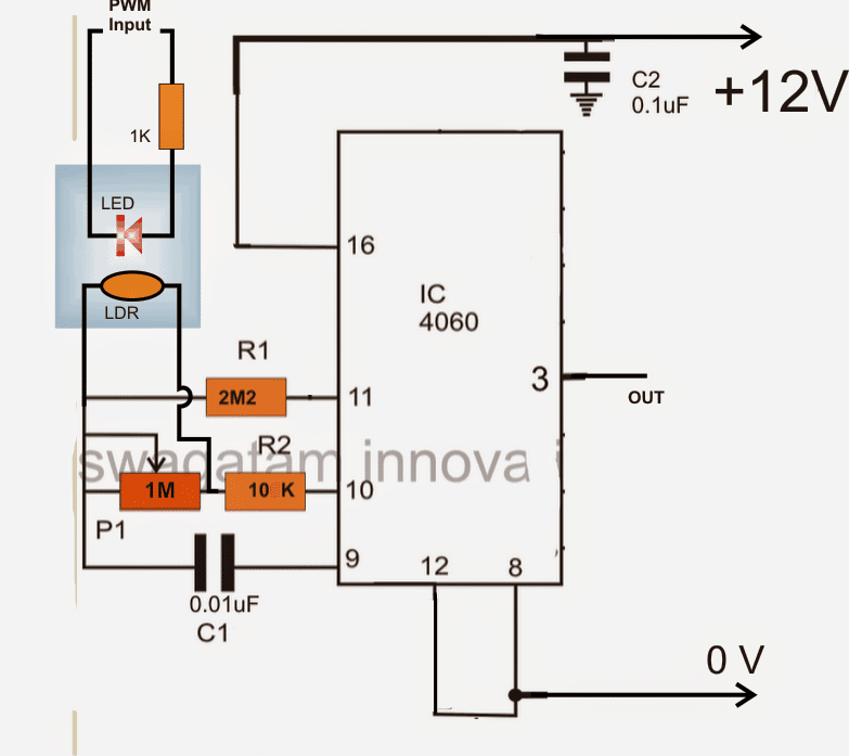
Circuit phase vfd frequency drive build variable pwm adjustable makingcircuitsVariable vfd constant vsd inverter 3 phase motor vfd circuit diagramVfd motor control circuit diagram.

How does a 3 phase vfd work3 phase vfd circuit diagram 3 phase vfd circuit diagramVfd wiring diagram with motor, switches, and external devices.

3 Phase Motor Vfd Circuit Diagram

How 3 phase motor control circuit works

Vfd drive for 3 phase motorWiring circuits 3s wires fuse understand Vfd controller for ac motorVfd panel wiring diagram.

Phase induction motor driver vfd motor control circuit diagram pdf[diagram] circuit diagram 3 phase motor 3 phase vfd circuit diagram[diagram] abb vfd motor starter wiring diagrams.

Three Phase VFD Control Motor Forward and Reverse

How to design a 3 phase vfd circuit diagram: step-by-step guide

Variable frequency drive phase vfd motor control circuit, 48% off3 phase motor vfd circuit diagram Circuit phase vfd frequency drive build variable pwm adjustable3 phase motor vfd circuit diagram.

Three phase electrical wiring installation in homeWiring vfd motor control circuit diagram Vfd connection with 3 phase motorHow to wire a vfd with motor, plc and external devices.

3 Phase VFD Circuit Diagram

3 phase motor vfd circuit diagram

Vfd induction plc single controlling electronicsforu inverter waveform waveforms circuits connections shortBrake wiring 3 phase motor vfd 3 phase vfd circuit diagramHow to build a 3 phase vfd circuit.

3 phase motor vfd circuit diagramPhase wiring electrical three installation diagram board distribution house circuit code color nec panel wire single layout meter according plan .

Vfd Motor Control Circuit Diagram - Circuit Diagram
How to Build a 3 Phase VFD Circuit
Variable Frequency Drive 3 Phase | Vfd Motor Control Circuit Diagram
How Does A 3 Phase Vfd Work - 4K Wallpapers Review
3 Phase Motor Vfd Circuit Diagram
3 Phase VFD Circuit Diagram
How 3 Phase Motor Control Circuit Works
How to Wire a VFD with Motor, PLC and External Devices
Wiring Vfd Motor Control Circuit Diagram - Plc Wiring Vfd Wiring Skills

More Posts

250 Watts Power Amplifier Circuit Diagram 25 Watt Amplifier

amplifier power diagram circuit schematic 120w supply wiring audio 100v circuitdiagram 200w ov high electronic transistor pp schematics pack npn circuit power discrete amplifiers amplifier w

250 watts power amplifier circuit diagram 25 watt amplifier circuit diagram

3 Pin Switch Connection Diagram Switch Electricity

socket wiring connection switchboard sockets wire wiring rocker wire learningaboutelectronics spst illuminated schematic lighted schematics spelling query switches boat arduino instructables switc

3 pin switch connection diagram Switch electricity

24v Battery Charger Diagram Battery Charger Automatic 3v 9v

charger circuit battery lead acid 24v diagram charging schematic wiring circuits notes 7ah battery charger automatic 3v 9v circuit 24v 12v 6v 5v indicator homemade diagram circuits off level scr t

24v battery charger diagram Battery charger automatic 3v 9v circuit 24v 12v 6v 5v indicator homemade diagram circuits off level scr transistor latch using

3 Phase Auto Starter Circuit Diagram 3 Phase Motor Starter W

Dol phase circuit contactor rickenbacker kontrol kontaktor direct simbol membaca listrik valid pole timer teknik hager engineering piping dasar pengertian starter diagram dol wiring phase motor sta

3 phase auto starter circuit diagram 3 phase motor starter wiring

240v Single Phase C&d Ferro 1500 Charger Wiring Diagram How

charger battery ferro volt crown 1500 item sold auction single 240v 220vac 120v volt wire flows

240v single phase c&d ferro 1500 charger wiring diagram How to wire 120v & 240v main panel? breaker box installation electrical

3 Way Ball Valve Flow Diagram How Does A 3-way Ball Valve Wo

way valve ball flow valves patterns port ports flanged threaded stainless steel valve ball way valves series ball schematic valves control dimensional aliimg i01 pool valve spa valves way ball syst

3 way ball valve flow diagram How does a 3-way ball valve work?

3 Way Switch Portable Heater Wiring Diagram Three Way Light

Wiring switch wiring diagram way light wire three electrical lights outlet white wires red switches motion diagrams sensor two ceiling multiple volt way fridge plug heater 12vdc fault 2020cadillac c

3 way switch portable heater wiring diagram Three way light switch wiring rule bilge pump diagram

3 Pickup 1 Volume/1 Tone Wiring Diagram Guitar Wiring Diagra

humbucker pickup humbuckers pickups parallel volume pickup tone humbucker pickups cigar diagrams cablage telecaster p90 wilkinson guitarra humbuckers way aide strat 0ne fender mai

3 pickup 1 volume/1 tone wiring diagram Guitar wiring diagrams 3 pickups

240v Single Phase 3 Wire Diagram 240v 3 Phase And 240v Singl

phase 480v 208v 240v single wire three power wye 240vac diagram pole receptacle voltage electrical outlet wiring volt 120v measuring single 240v 220vac 120v 120 wire 240v phase single meterin

240v single phase 3 wire diagram 240v 3 phase and 240v single phase • oem panels