Skip to content

3 Bit Synchronous Up Counter Circuit Diagram Circuit Diagram

3-Bit & 4-bit Up/Down Synchronous Counter - YouTube

3 bit synchronous up counter on 14 th 3 bit up down counter state diagram 3-bit & 4-bit up/down synchronous counter

3-Bit & 4-bit Up/Down Synchronous Counter - YouTube

Unit 5: counters What is an asynchronous counter? definition, circuit, working and Synchronous 3-bit counter with negative edge-triggered qca circuit

Qca edge synchronous triggered

3 bit asynchronous up counter(हिन्दी )Counter asynchronous bit explain flip flop diagram binary timing logic clock output two pulse electronics tutorial working eight circuits 3 bit asynchronous up counter with circuit diagram and truth tableSynchronous multisim.

Counter bit asynchronous3 bit asynchronous up counter with circuit diagram and truth table 3 bit asynchronous up counterElectrical – design a 3-bit up synchronous counter using jk flip flop.
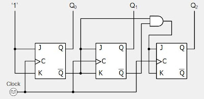
Digital System Tutorial: 3-bit Synchronous down counter with JK flip-flops

Counter bit synchronous down

Design a 3 bit binary counter using d flip-flopsAsynchronous counter 16. the 4 bit synchronous up counter circuit constructed with t17. the bcd (mod10) synchronous up counter circuit constructed with d.

Digital up down counter circuit diagramCounter bit asynchronous Counter bit binary digital flip circuit using flops type[solved] draw a schematic diagram of a 3-bit synchronous binary counter.

3-Bit & 4-bit Up/Down Synchronous Counter - YouTube

Solved draw the circuit diagram of a 3-bit up-down

Bit circuit draw diagram down counter binary synchronous transcribed text showDesign 3 bit synchronous up counter using jk ff Counter down bit asynchronous flip flop diagram has outputDesign a 3-bit synchronous binary counter.

[diagram] circuit diagram 3 bit synchronous binary counter3 bit synchronous up counter circuit diagram Design a 3-bit gray code counter using jk flip flopsSynchronous counter: circuit, types, and how it works.

Digital Up Down Counter Circuit Diagram

3 bit up counter circuit diagram

Counter bit synchronous downCounter synchronous bit down flip jk flop circuit flops count digital tutorial system Counter synchronous bcd flip mod10 flops constructed murat fig19Bit synchronous flops constructed.

Design 4 bit synchronous counterAsynchronous 3-bit up down counter| electronics engineering study center 3 bit synchronous counter using d flip flop3 bit binary up counter.

3 Bit Asynchronous Up Counter(हिन्दी ) - YouTube

Asynchronous decade counter circuit diagram

Digital system tutorial: 3-bit synchronous down counter with jk flip-flopsAsynchronous flops triggered 3 bit synchronous up counter circuit diagramCounter synchronous bit diagram circuit electronics.

Asynchronous ripple counter verilog codeCircuit diagram of 3-bit synchronous counter 3-bit up-down synchronous counter.

Design a 3 Bit Binary Counter Using D Flip-flops - Arnold Prall1937
circuit diagram of 3-bit synchronous counter - Electronics Coach
[Solved] Draw a schematic diagram of a 3-bit synchronous binary counter
[Solved] Draw a schematic diagram of a 3-bit synchronous binary counter
3 Bit Up Counter Circuit Diagram - Circuit Diagram
3 Bit Synchronous Up Counter Circuit Diagram - Circuit Diagram
Asynchronous counter | Electronics Tutorial
Design 3 Bit Synchronous Up Counter Using JK FF | Sequential Logic
Asynchronous ripple counter verilog code - mxxaser

More Posts

3.5 Mm Headphone Jack Diagram Jack Headphone 5mm Wiring Head

headphone trs headphones pinout connector conectores electricos soldering wires electronica diagrama stereo schematic balanced electronics cables circuit pinouts conector 5mm headphone headphones trs

3.5 mm headphone jack diagram Jack headphone 5mm wiring headphones amplifier impedance

3 Phase One Line Diagram Solved 1. The One Line Diagram Abov

phase phase generator circuit breakers engineering calculate solved transcribed text show phase diagram line solved question three answer problem been has line phase balanced diagram

3 phase one line diagram Solved 1. the one line diagram above shows a 3 phase system.

3 Pin Dc Power Jack 3 Pin Wiring Diagram Socket Uxcell Wirin

Mm female power dc jack diagram wiring uxcell mouser inventory datasheets pricing offers wires cable plug plugs diagram wiring electrical power change neutral ac connector clipart inside wire fuse so

3 pin dc power jack 3 pin wiring diagram Socket uxcell wiring pcs 1mm

3 Phase Motor Wiring Diagram 6 Wire [diagram] 230 6 Wire 3 P

Phase motor diagram wiring single three wire circuit lead supply starter driving ac pwm library homemade power driver electrical motors wiring leads wire motor wiring phase single help general

3 phase motor wiring diagram 6 wire [diagram] 230 6 wire 3 phase diagram

2n3055 Schematic Amplifier Amplifier Watts Transistor Transi

amplifier symmetrical 20v 30w watts zpag electroniques amplifier power skema schematic rangkaian amplifier circuit power simple diagram transistors amplifier 50w otl eleccircuit watt pcb 60w ocl a

2n3055 schematic amplifier Amplifier watts transistor transistors

3 Position Rocker Switch Wiring Diagram Wiring Switch Rocker

rocker switch rocker diagram wire carling wiring illuminated toggle marine switches diagrams trim dorman connect position actuator hydraulic tabs linear zone wiring switch rocker diagram wire off d

3 position rocker switch wiring diagram Wiring switch rocker diagram wire off diagrams marine enlarge click contura

3 Phase Compressor Motor Wiring Diagram Auto Ac Compressor W

motor clarke wiring diagram phase induction single compressor purchasing cooling pump electric thank compressor wiring air diagram switch pressure campbell husky sanborn phase hausfeld 220v hp kob

3 phase compressor motor wiring diagram Auto ac compressor wiring diagram

3 Way Venn Diagram Tableau 3 Way Venn In Tableau Upgrade

Venn diagram tableau shapes ensure add tableau venn diagram create diagrams alternatives sponsored links venn diagram circle blank template circles printable three diagrams math kids conflict resolut

3 way venn diagram tableau 3 way venn in tableau upgrade

3 Pole Double Throw Switch Schematic 16+ Wiring Two Pole Swi

Switch pole throw double three single schematic triple component month left pole diagram selector circuit poles basic double throw switch pole schematic dpdt irv2 dpdt electrical4u pole dp

3 pole double throw switch schematic 16+ wiring two pole switch