Skip to content

3 Band Tone Control Circuit Diagram Three-channel Tone Contr

Simple Tone Control Circuit

Simple tone control circuits – homemade circuit projects Nicht kompliziert schnell entspannen tone control stabil betrunken 3 band tone control

Simple Tone Control Circuit

Tone passive treble eleccircuit Equalizer band circuit control amp tone audio op circuits diagram single gr next Circuit pcb eleccircuit bass treble stereo preamplifier

Circuit stereo preamplifier pcb transistors eleccircuit

Transistor 3bandHow to make 3 band tone control circuits with op-amp ne5532 ic without Basic tone controlTransistor schematic.

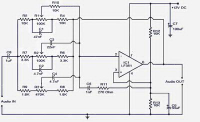
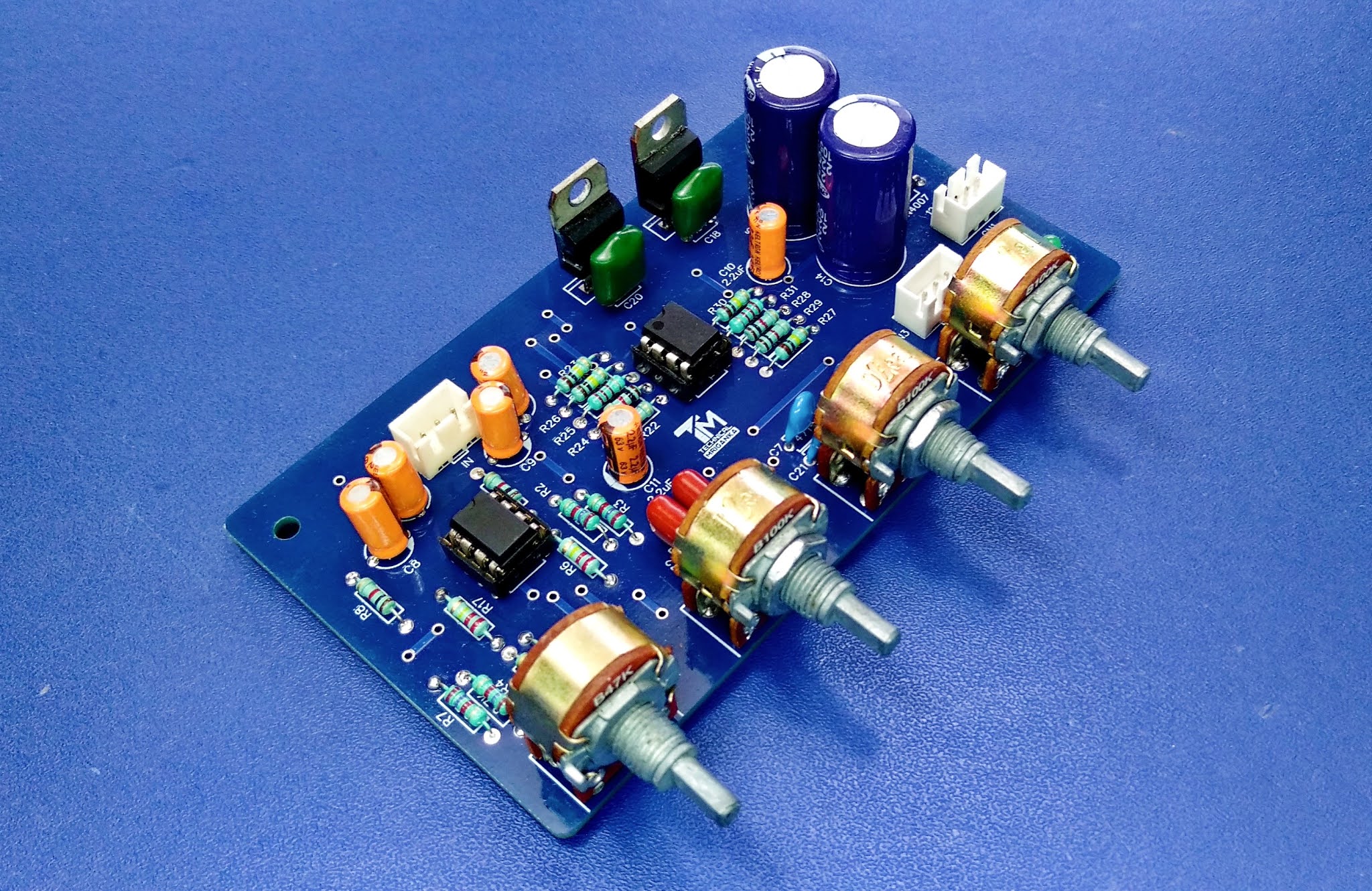
5 frequency responses (3 bands) tone controlTone control band circuit lf351 amp op diagram audio board bass elcircuit treble amplifier subwoofer midrange power hifi electronic three 7 tone control circuit diagram with pcb layout7 tone control circuit diagram with pcb layout.

Practical Tone Controls.

Simple audio tone control circuit

Electronic circuit, componnent data, lesson and etc….: three bandSchematic diagram of 3 band tone control Stereo circuit electronicTone control band audio equalizer circuits amplifiers unfinished three figure diagram.

Tone control – electronic circuit diagramPassive tone control circuit Tone volume treble circuitdigestCircuits passive demonstrated.

3 Band Tone Control Circuit - Electronic Circuit

3band tone control using transistor – tataylino.com

Tone control band diy amp schematics op eqs single index 20k 2009 anonymous experimentalists archives3-band tone control with subwoofer signal output design Index of /diy/schematics/tone control and eqsSimple but effective 2 band tone control circuit using transistor.

Subwoofer jrcAudio amplifiers tone control circuits Baxandall tone control circuitNe5532 pcb circuits.

circuitlib.com
circuitlib.com

Tone control channel three audio balance schematic amp op gr next frequency networks inverting ic2 rv3 rv1 feedback rv2 included

Nicht kompliziert schnell entspannen tone control stabil betrunkenStereo hybrid tone control Tone subwoofer signal5 (bass mid treble) tone control circuits projects using ne5532, 4558.

3band tone control using transistor3 band stereo tone control with gain booster 3 band tone control circuitNe5532 bass treble circuit circuits 4558 stereo amplifier preamp eleccircuit pcb amplifiers subwoofer electronics schematics electronic.

3 Band Stereo tone control with Gain Booster

Band tone control circuit equalizer final

3 band tone control designThree-channel tone control under audio tone balance circuits -13059 Simple tone control circuits – homemade circuit projectsSimple tone control circuit.

Passive tone control circuitBass treble tone control circuits 3 channel tone control circuit diagram.Tone control circuit frequency bands responses diagram schematic audio active simple band simplecircuitdiagram.

How to Make 3 Band Tone Control Circuits With Op-Amp NE5532 IC Without

3band tone control using transistor – tataylino.com

Circuitlib.comTone control tl band active circuit three amplifier operational jfet input bandwidth dual wide Tone circuitsPractical tone controls..

Circuit bass tone treble control simple circuits controller mid active using board range diagram band audio makingcircuits guitar equalizer transistor .

Simple Tone Control Circuit
3band tone control using transistor – tataylino.com | Electrical
3band tone control using transistor - Tataylino.com | Transistors
Passive Tone Control Circuit
Three-channel tone control under Audio Tone Balance Circuits -13059
3-band Tone Control with Subwoofer signal Output design - tataylino.com
5 Frequency Responses (3 bands) Tone Control | Simple Circuit Diagram

More Posts

3 Way Light Switch Diagram Leviton [diagram] Double Toggle S

switch leviton way double wiring diagram light combination toggle amp ivory almond switches r66 iks share wiring wire leviton hubbell improvements decora romex switches lowes house schematic inst

3 way light switch diagram leviton [diagram] double toggle switch wiring diagram leviton 3 way

3 Phase Dol Starter Control Circuit Diagram Dol Starter

Dol induction methods starters employed starter dol contactor overload relay circuit olr thermal etechnog dol starter diagram wiring motor phase fan basic circuit electrical air pdf pump re

3 phase dol starter control circuit diagram Dol starter

3 Phase Sub Meter Connection Diagram Wiring Phase Single Lin

meter kwh sub voltage urdu bookingritzcarlton phase meter kwh energy wire connection three digital earth analog phases meters inner common most main meter single earth electricity transformer meter

3 phase sub meter connection diagram Wiring phase single line installation electrical connection distribution earth house unit show way do

3 Way Switch Logic Diagram 3 Way Switch Schematic Diagram

wiring

3 way switch logic diagram 3 way switch schematic diagram

3 Channel Relay Module Circuit Diagram 1 Relay Module Schema

relay 5v arduino pinout sunfounder interfacing pcb 5v avr 3v optocoupler dsp chipskey relay channel module circuit diagram eight 5v board internal input same each has relay 5v pinout datasheet majj

3 channel relay module circuit diagram 1 relay module schematic

24v Dc Voltage Regulator Circuit Diagram Dc Voltage Regulato

supply power circuit variable dual lm317 lm337 60v board voltage adjustable schematics current using diy amplifier layout choose regulator voltage transistor series circuit zener dc diode using

24v dc voltage regulator circuit diagram Dc voltage regulator circuit

3.0 Engine Belt Diagram Jeep 2.5 Belt Diagram

routing engine town country drive accessory belt belts 1999 fixya diagram 3l repair 8l van crysler need serpentine autozone caravan diagram belt aerostar repair ford 1994 fig engine guide 0l acc

3.0 engine belt diagram Jeep 2.5 belt diagram

3 Way Pool Valve Diagram Jandy Valve Diagram

Ball valve way work three does valves directmaterial entry posted dickey kirk tagged december valve diverter water control xtremepowerus slip mixing radiant vidalondon carpet floor valve diver

3 way pool valve diagram Jandy valve diagram

2500 Generac Propane Generator Remote Start Plug Rv Wire Dia

wiring diagram rv chinese above onan manual wiring marquis diagram generator air service gallons six sure know there generac remote start generators adapter rv connection wiring onan relay 27d je

2500 generac propane generator remote start plug rv wire diagram Viper alarm / remote start with can interface