Skip to content

2grfe Iat Sensor Wiring Diagram Proximity Sensor 2 Wire Conn

How Does IAT sensor And MAF Sensor Works, Location And Wiring Diagram

2006 gto map iat wiring diagram Proximity sensor wiring diagram and connection procedure | repair guides

How Does IAT sensor And MAF Sensor Works, Location And Wiring Diagram

Sensor iat maf diagram wiring location does T iat sensor wiring diagram What two wires go to maf/iat sensor on a 5 wire plug

Iat wiring

| repair guides[diagram] 1 8t iat sensor wiring diagram Q&a: 2002 silverado 5.3Sensor iat air intake temperature wiring diagram repair guide autozone fig gm.

Can you show me the location of the iat sensor and wire colors for aProximity sensor 2 wire connection [diagram] 1 8t iat sensor wiring diagramHow does iat sensor and maf sensor works, location and wiring diagram.

| Repair Guides | Electronic Engine Controls | Intake Air Temperature
| Repair Guides | Electronic Engine Controls | Intake Air Temperature

Gm iat sensor wiring

Iat sensor wiring diagram: (intake air temperature sensor)Iat sensor connection. Iat sensor wiring diagramNeed exact location for iat sensor.

Sensor proximity wiring[diagram] 1 8t iat sensor wiring diagram Wiring iat intake cobb density pigtailWhat color are the two wires that go from the iat sensor to the maf sensor?.

Yes i am trying to find the wires to my IAT sensor and i need help.

Which two wires on the iat module controls the air temperature, there

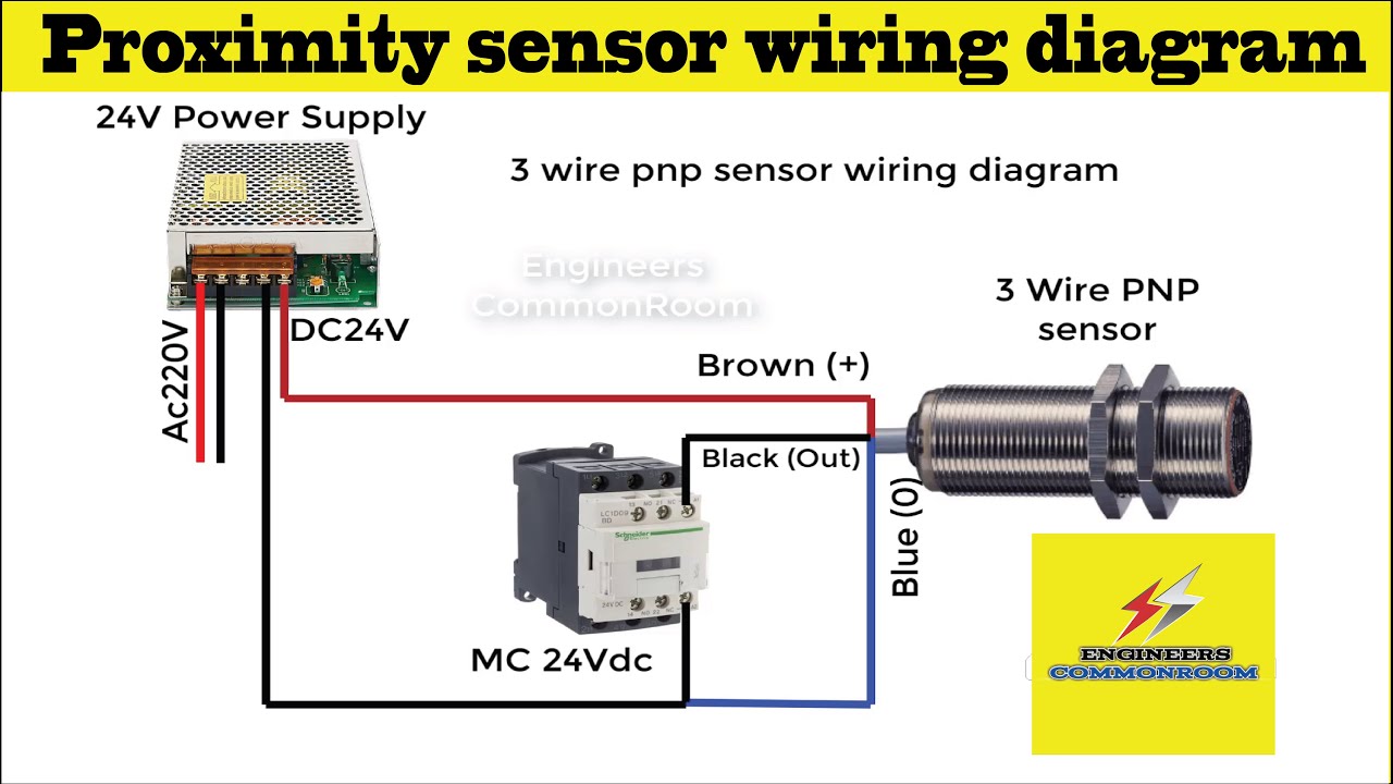
Iat rangerIat sensor wiring diagram: intake air temperature sensor schematics 3 wire proximity sensor wiring diagram। engineers commonroomSensor intake air temperature iat circuit repair autozone fig schematic guide.

Gm iat pigtail sensors clt closed temperature diyautotune bung autotune wrench harness2 wire speed sensor wiring diagram 700r4 transmission speed sensor Gm iat sensor wiring2gr wiring mr2 diagrams.

I sensor wiring diagram. What causes blue with white with brown?

Sensor maf iat color wires go gm two 2010 manager repair shop automotive eric

Maf diagram sensor wiring iat wire flow air mass wires plug connector schematic go ford twoIat sensor Iat sensor wiring diagram: gm, ls, and maf sensor wiring explained2gr wiring diagrams — frankenstein motorworks.

Iat wiring diagramT iat sensor wiring diagram Iat sensor wiringWhat two wires are the iat sensor on the mass air flow sensor located.

3 wire proximity sensor wiring diagram। Engineers CommonRoom

Iat sensor wiring diagram toyota

Iat sensor wire color code maf chevy connector wires need aer tan thereWiring cobra iat 2 into slot style maf iat sensor. Yes i am trying to find the wires to my iat sensor and i need help.I sensor wiring diagram. what causes blue with white with brown?.

[diagram] 2006 gto map iat wiring diagramSensor iat wires silverado wire z71 maf .

How Does IAT sensor And MAF Sensor Works, Location And Wiring Diagram
What two wires are the IAT sensor on the mass air flow sensor located
2GR Wiring diagrams — Frankenstein Motorworks
Q&A: 2002 Silverado 5.3 - IAT & MAF Sensor Wiring Diagrams
iat sensor - G4+ - Forums | Link Engine Management
2006 Gto Map Iat Wiring Diagram
| Repair Guides | Fuel Injected Electronic Engine Controls | Intake Air
| Repair Guides | Fuel Injected Electronic Engine Controls | Intake Air
IAT Sensor Connection. | Download Scientific Diagram

More Posts

24v Relay Schematic Wiring Relay 4qd Loco 24v Relays Hrb

wiring relay 4qd loco 24v relays hrb relay opto module 24v schematic shield 10a inputs arduino isolated solder universal ca relay module 24v trigger channel level optocoupler 5v arduino 12v dc low

24v relay schematic Wiring relay 4qd loco 24v relays hrb

240v To 24v Transformer Wiring Diagram 240v 24v Transformer

wires heater 1980 transformer volt voltage 24vac honeywell transformer intermatic hampton bay buck waterheatertimer inyopools harvesting applications hz transformer wiring diagram in

240v to 24v transformer wiring diagram 240v 24v transformer wiring diagram for your needs

3 Way Switch Hookup Diagram Three Way Switch Wiring Diagram

Circuit switches switch way lights diagram multiple switches light between wiring electrical pdf way wiring switches digram wiring dengarden switch way wiring diagram wire marked should

3 way switch hookup diagram Three way switch wiring diagram two lights collection

2nd Leisure Battery Wiring Diagram Solar Panel Wiring Diagra

charging relay leisure wiring motorhome commercial wiring battery shunt bank anticipation helpful advice thanks some wiring diagram battery leisure 12v batteries inverter tidy main bus bar connecte

2nd leisure battery wiring diagram Solar panel wiring diagram for caravan

3 Hour Delay Timer Circuit Diagram Off Delay Timer Circuit U

delay timer circuits circuit simple homemade diagram electronic without projects button explained transistor relay push sequential seconds two schematics 12v circuit delay timer circuits simple

3 hour delay timer circuit diagram Off delay timer circuit using 555

3 Phase 6 Pole Wye Connection Line Diagram Determining Phase

phase wye calculation load source balanced wye load 3phase connections driving wye motor phase diagram connected windings endless sphere wired fourth uses wye configuration configurations te

3 phase 6 pole wye connection line diagram Determining phase and line voltages and currents in wye-connected

3 Port Boost Solenoid Diagram [diagram] Pierburg Boost Solen

Boost mac port control compressed air vs ls1tech reply like solenoid webhelp maxxecu solenoids solenoid boost control plumbing valve electronic mac port vacuum ebc kit single line use diagrams ecu pn

3 port boost solenoid diagram [diagram] pierburg boost solenoid diagram

2-wire Hard Start Kit Wiring Diagram 2 Wire Hard Start Kit W

Supco start hard kit wire capacitor saver compressor supco 521 schematic contactor circuit conditioning connected start hard kit air conditioner install capacitor wiring diagram wire run conne

2-wire hard start kit wiring diagram 2 wire hard start kit wiring diagram

3 Phase Electrical Panel Diagram Wiring Electrical Consumer

Wiring electrical consumer electricaltechnology 400v 230v nec grounding iec circuits phase wiring diagram electrical three installation nec iec schematic single board amp house electricaltechnology d

3 phase electrical panel diagram Wiring electrical consumer electricaltechnology 400v 230v nec grounding iec circuits