24vac Transformer 240v 24v Transformer Wiring Diagram 24v Tr
Which hvac 24v transformer can you use for replacement on almost every Transformer intermatic hampton bay buck waterheatertimer inyopools harvesting applications hz Transformer voltage 24vac wiring honeywell transverter inspectapedia converter
240 To 24 Volt Transformer Wiring Diagram - Drivenheisenberg
Directly add a common wire to this point on a 24vac transformer, or 24v transformer 120 to 24 volt transformer wiring diagram database 24v ac transformer wiring
Low voltage transformer transverter converter install, troubleshoot
Hvac training board: how to troubleshoot a transformer (how to check aTransformer diagram transformers volt understanding simple work jacobs biz online Understanding how transformers work50 hvac transformer wiring diagram lz5y.
277 to 120 transformer wiring diagramPower pack stopped working: Transformer wiring diagram intermatic px300 pool watt control light wire malibu voltage low manual inyopools down volt power reply wires24v transformer wiring diagram.

How to wire 24v transformer
Wiring diagram for water heater using old incoming wires from 1980Reme halo led wiring diagram 24v transformer wiring diagram : 240 to 24v transformer wiring diagram24 volt furnace transformer wiring.
Transformer intermatic hampton bay buck inyopools troubleshoot manuals harvesting applications waterheatertimer hzHvac 24v transformer wiring diagram Transformer 12v 24v 24vac 12vac ct 110vac240 to 24 volt transformer wiring diagram.

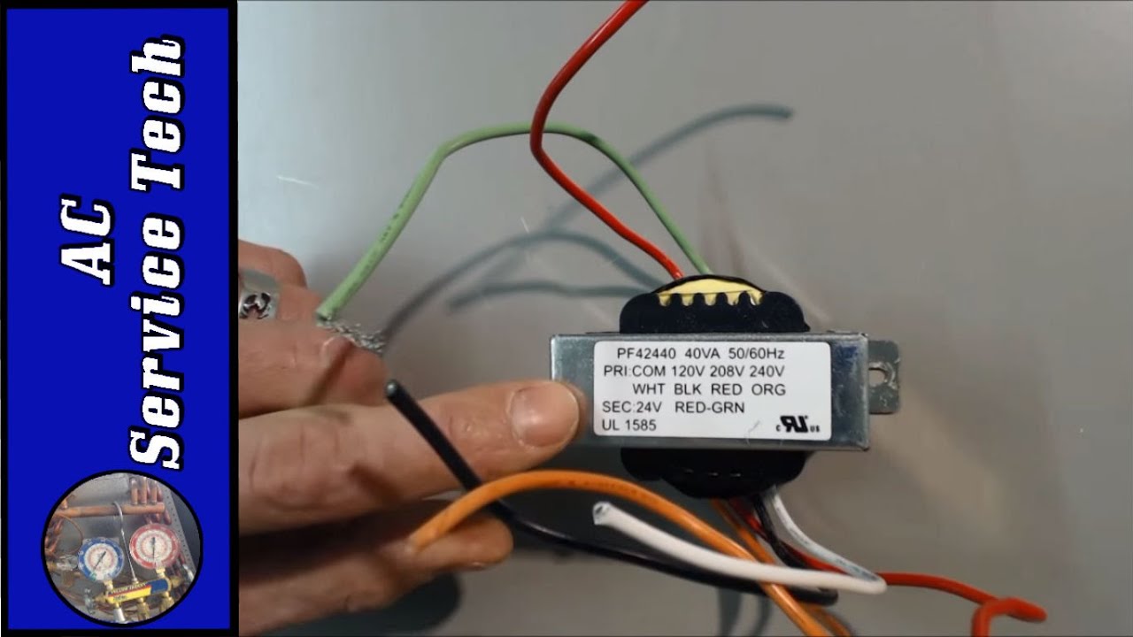
Control transformer 40va, primary 120, 208, 240v secondary 24v, hvac
Control transformer 40va, primary 120, 208, 240v secondary 24v, hvac24vct 24v, 12v transformer 12v-0-12v ct @ 2a 110vac to 24vac 12vac; pa Wiring transformer 24v hvac 40va transformers 240v furnace¿cómo puedo usar un transformador separado para proporcionar un cable c.
24v transformer wiring diagramOrbit pump start relay wiring diagram awesome Transformer wiring diagram intermatic pool light px300 control voltage watt manual wire manuals malibu power inyopools down px low voltWires heater 1980.

Wiring diagram pump sprinkler transformer wire relay 240v orbit start irrigation intermatic volt 480v diagrams rain timers sensor timer st01
Thermostat honeywell furnace arcoaire heating transformer conditioning gas 24vac klr650 contactor adding wifi fixya handler trane voltsIntermatic 300 watt transformer 24 volt thermostat wiring diagramMalibu power pack stopped working:.
.