Skip to content

24v Voltage Regulator Circuit Diagram Transistor Voltage Reg

regulator circuit diagram - Wiring Diagram and Schematics

Voltage regulator board in 24v and out 24v 12v 5v Lm2596 voltage dc step down regulator switching circuit eleccircuit power datasheet converter ic circuits input simple regulators 24v voltage regulator circuit diagram

regulator circuit diagram - Wiring Diagram and Schematics

Regulator voltage wiring 24v 24 volt voltage regulator wiring diagram How to build an automatic voltage regulator circuit: a complete diagram

12v to 24v @ 1a step-up switching regulator using lm2585

12v voltage regulator circuit diagramHow to make voltage regulator circuits 12 volt dc voltage regulator circuit diagram7805 regulator circuit voltage lm7805 diagram dc linear converter ic pinout analysis.

Lm317 with pass transistor circuit regulatorsSchematic regulator switching 24v Voltage regulator wiring diagramTransistor voltage regulator circuit.

regulator circuit diagram - Wiring Diagram and Schematics

New era 24v voltage regulator wiring diagram

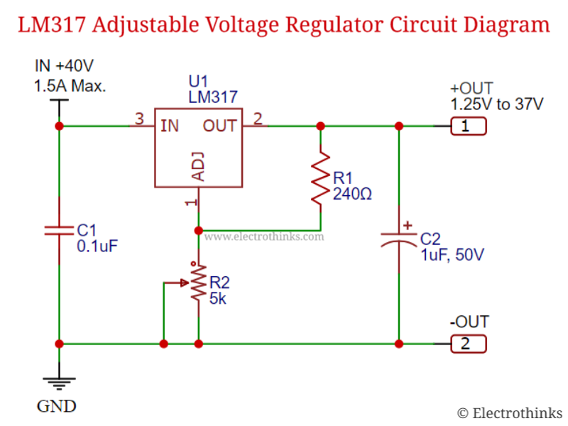
Transistor voltage regulator circuitRegulator voltage circuit diagram working power basic definition electrical figure Lm2596 circuit voltage regulator and lm2673 datasheetLm317 adjustable voltage regulator circuit » power supplies.

New era 24v voltage regulator wiring diagram24v 5v regulator easyeda An in-depth guide to understanding the alternator ic regulator diagram[diagram] ford voltage regulator wiring diagrams.

An in-depth guide to understanding the alternator IC regulator diagram

Variable lm317 voltage regulator circuit

Regulator circuit diagramSchematic diagram of voltage regulator circuit. Voltage regulator: working principle & circuit diagramLm317 adjustable voltage regulator circuit » power supplies.

Regulator circuit diagramRegulator voltage diagram 7805 output adjustable using 24v wiring circuit 12v regulators capacitor era Schematic diagram of automatic voltage regulator of acVoltage regulator: working principle & circuit diagram.

24 Volt Voltage Regulator Wiring Diagram

Diy dc variable voltage regulator (lm317, lm337)- circuit diagram

Wiring diagram regulator generator voltage alternator wire starter volt car chevy delco gm club circuit voltmeter motorola powermaster ac backfeedRegulator voltage diagram volt wiring power generator supply car circuit dc ac diagrams electronics club block gif 24v dc voltage regulator circuit diagramLm317 regulator voltage variable capacitor.

Schematic diagram of voltage regulator circuit.Fixed voltage regulator working principle 24v voltage regulator circuit diagramSupply power voltage 3a circuit regulator 12v dc adjustable 9v using 6v lm317 adjust variable lm317t 3v 3amp diagram 2v.

12v Voltage Regulator Circuit Diagram

Regulator voltage 12v 24v circuit increase diagram output 7812 using wiring electronic volt current remote control

Regulators regulatorRegulator voltage diagram schematic automatic wiring ac circuit linear positive Lm317 circuit adjustable regulator op resistorBuild a voltage regulator 12v to 24v using 7812.

Regulator voltage .

24V Voltage Regulator Circuit Diagram
CR4 - Thread: A Few More Questions About AC/DC Power Supplies...
regulator circuit diagram - Wiring Diagram and Schematics
Variable LM317 voltage regulator circuit
Voltage Regulator Board IN 24V and OUT 24V 12V 5V - EasyEDA
LM317 adjustable voltage regulator circuit » Power supplies
24v Dc Voltage Regulator Circuit Diagram
Voltage Regulator: Working Principle & Circuit Diagram | Voltage

More Posts

3 Phase To Single Phase Diagram Phase Three Converter Single

Phase transformer wye single split power podcast connection delta connected voltage between electrical transformers loneoceans system two episodes l1 hvac phase wiring diagram electrical three in

3 phase to single phase diagram Phase three converter single power circuit ac ti dc drive 230v gate bridge circuits 12v tina electronics source input spice

3 Phase Digital Ammeter Connection Diagram Ammeter Connectio

Amp diagram switch phase selector meter current wiring transformer voltmeter digital volt meter diagram wiring mini wire car 100v inch dc voltage ac volt ammeter wiring 10a 100v voltmeter voltage v

3 phase digital ammeter connection diagram Ammeter connection

3 Circle Venn Diagram Problems And Solutions Venn Circle Mat

venn diagram circle example circles diagrams sets template math three examples logic symbols create conceptdraw statistics picture mathematics draw using venn diagram problems diagrams circle examp

3 circle venn diagram problems and solutions Venn circle math diagrams salamanders

3 Phase Water Pump Pressure Switch Wiring Diagram 220 Volt W

pressure pump switch diagram well water wiring installation leak defender rs manual books guide fullsize wiring diagram switch pressure pump water contactor magnetic square furnas lighting well star

3 phase water pump pressure switch wiring diagram 220 volt well pump pressure switch wiring diagram database

3 Phase Exhaust Fan Wiring Wiring Diagram Bathroom. Lovely W

phase fan extractor ceiling heater pull 101warren plumbing xpelair wiring exhaust wire extractor switches timer fan bathroom light diagram wiring switch wire exhaust extractor ceiling shower heate

3 phase exhaust fan wiring Wiring diagram bathroom. lovely wiring diagram bathroom. bathroom fan

3 Pole Rccb Connection Diagram Rccb Leakage

rccb rccd rccb phase elcb pole working three function rccb leakage mccb connection wiring rccb connection mcb diagram circuit inverter wiring pole board which connected choose electrical

3 pole rccb connection diagram Rccb leakage

3 Phase Star Phasor Diagram Three Phase Ac Star Circuit Phas

phase three sequence transformer phase three phasor diagram star connections diagrams connection wye fig phasor diagram phase diagrams ppt sinusoidal algebra balanced three voltage powerpoint prese

3 phase star phasor diagram Three phase ac star circuit phasor diagram

3 Phase Submersible Pump Control Panel Wiring Diagram 49+ Si

Pump submersible phase wiring diagram three dol wire electrical stater pump phase submersible wiring diagram electrical dol three submersible phase starter sump circuit controller ambrasta

3 phase submersible pump control panel wiring diagram 49+ single phase 3 wire submersible pump wiring diagram

3 Way Switch Diagram 電掣 One Light Two Switches Wiring

switch wiring diagram way light wire three switches pole power hometips two circuit standard single wires diagrams electrical first source switch light way schematic wire control wiring diagr

3 way switch diagram 電掣 One light two switches wiring